Online Help
Main
Basics
("EFW for
dummies")
Validation
Pitfalls
EFW for Dummies
1. Hardware
2. Spheres
3. Iv curve
4. Current biasing
5. Modes
Related
EFW Home
Operations
|
3. The I-V Curve
So in equilibrium, the probe charges to whatever potential attracts enough photoelectrons back so that:
Photoelectron current + Plasma ion current = Plasma electron current.
Fine, but we'd presumably like to know what that potential is. For that,
we can consider each of the three currents separately, and ask how it's affected
if the probe potential changes. For now, we won't be concerned with
how the probe potential changes; imagine it as if we can simply set the potential
of the probe with respect to the plasma, and observe the currents that flow.
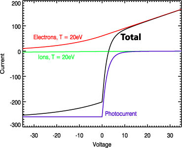
 The first current we'll consider is the photocurrent.
If the probe is negative with respect to the plasma around it, then
all of the liberated photoelectrons will flow out into space. This current
depends on the surface properties of the sphere and the solar illumination
only. For EFW, the maximum photocurrent is about 270 nA (as of
2002; this value is a function of time and solar cycle). If the probe
is positive, some fraction of these photoelectrons are attracted back to
the sphere, reducing the current as shown. Since the energy of the
emitted photoelectrons is very small, the net photocurrent falls rapidly
for potentials above 0. Above about 12 V, all of the photoelectrons
come back, and there is no net photocurrent.
The next current is the electrons.
If the probe is far negative with respect to the plasma (say -50 V
in the example here), effectively no electrons reach the probe. If
the probe is not quite so negative, some of the most energetic electrons
will reach the probe. As the potential rises, the current increases;
the shape of the curve depends on the temperature, and scales with the density.
Eventually, at 0 V, the full geometric cross-section of the probe is
struck by the electrons. The current here is a function of temperature
and density (see below). If the probe potential is positive, the probe
begins sucking in electrons from the surroundings. Above about +12
V, the only current is the electron current.
The third current is the ion current. For
EFW, this current can usually be neglected. It behaves essentially
exactly opposite to the electron current. At large positive probe voltages,
it is shut off. At 0 V, the full geometric cross section of the probes
is available, although since the ions move so slowly, the current is much
smaller than the electron current. At large negative voltages, the
probes suck in ions from the surroundings, resulting in a larger and larger
current. The current is in the opposite sense to the electron current;
you can see it just slightly at -35 V on the graph.
Of course, the probe can't separate the currents. It responds to the
total current, shown in black. In this example, if the probe were allowed
to float (i.e. no net current), then it would float at 2.90 V (the intersection
of the black curve with I=0). The equations for the curves are given
in the box below.
|
Technical detail:
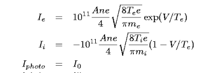
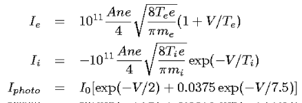
Equations for the IV curves, assuming a Maxwellian plasma, with the
Debye length much larger than the sphere radius are, for V < 0:

and for V > 0:

Where:
A is the probe area (cm^2) (50.25 for EFW)
n is density (cm^-3)
e is electron charge (C)
T_e and T_i are the electron and ion temperatures (eV)
m_e and m_i are the electron and ion masses (kg)
V is the probe voltage (V)
I_e and I_i are the electron and ion currents (nA)
I_photo is the photocurrent (nA)
I_0 is the maximum photocurrent (~270 nA)
Electron and ion currents are well-known from Langmuir theory. The photocurrent is from:
A. Pedersen, Solar wind and magnetospheric plasma diagnostics by spacecraft
electrostatic potential measurements. Annales Geophysicae, 13. 118-129.
1995.
|
Note:
This discussion holds equally well for the entire satellite as for
the probes. This is why the satellite potential can be used as a proxy
for the density.
|
Previous page
Up to table of contents
|

 The first current we'll consider is the photocurrent.
If the probe is negative with respect to the plasma around it, then
all of the liberated photoelectrons will flow out into space. This current
depends on the surface properties of the sphere and the solar illumination
only. For EFW, the maximum photocurrent is about 270 nA (as of
2002; this value is a function of time and solar cycle). If the probe
is positive, some fraction of these photoelectrons are attracted back to
the sphere, reducing the current as shown. Since the energy of the
emitted photoelectrons is very small, the net photocurrent falls rapidly
for potentials above 0. Above about 12 V, all of the photoelectrons
come back, and there is no net photocurrent.
